Kerbal Space Program controller build log 1 (2023-05-01)
A few years ago, I started playing Kerbal Space Program. For those who don’t know, KSP is a spaceflight simulation game in which you build rockets and spacecraft to send little green people called Kerbals around planets in a simulated solar system (and bring them back safely!). At some point, I saw on reddit that players were building custom control panels for the game, and it made me want to try my hand at building my own. This project lingered in the back of my head for a while, but recently I had a inexplicable surge of motivation to work on it again.
I plan to do a “build log” of sorts, with this post being the first entry. It’s mostly a dump of inspirations, experiments, construction details and rants, but there might be useful tidbits here and there.
Inspiration
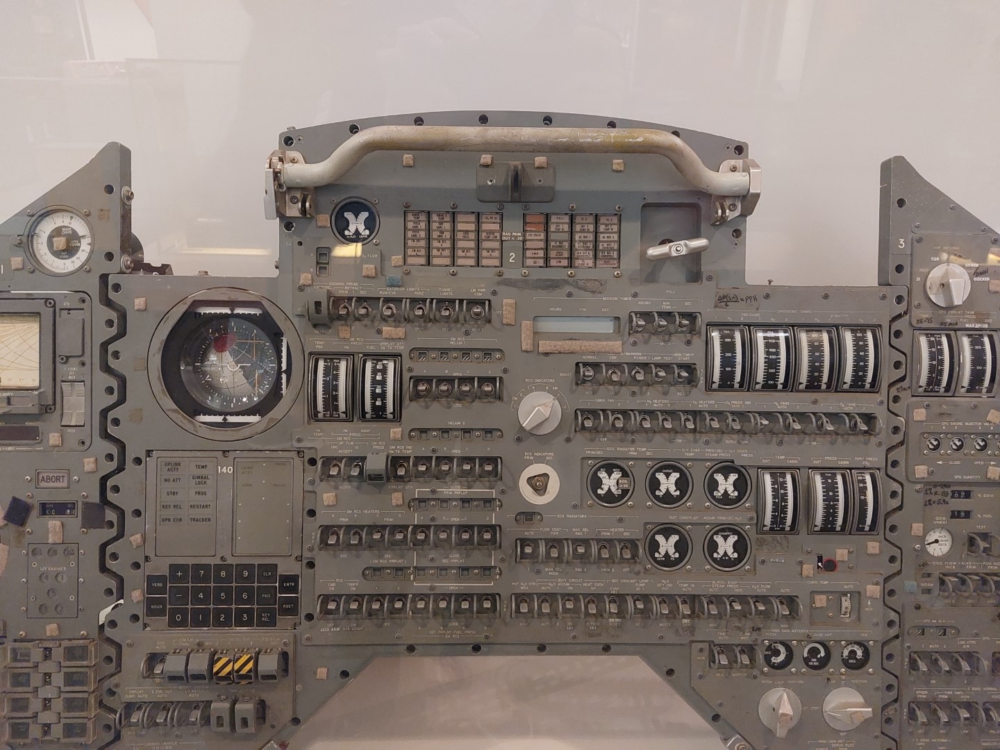
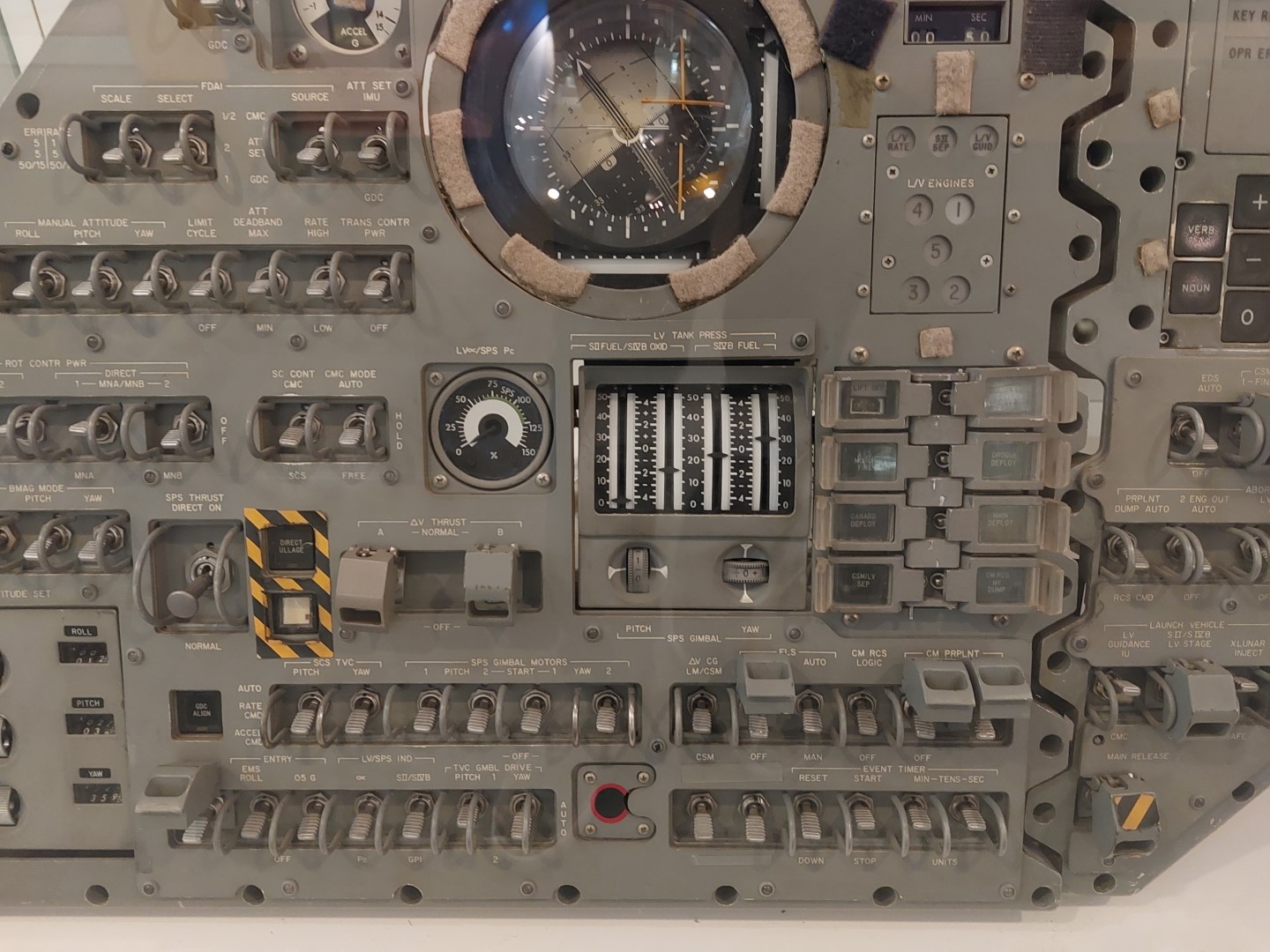
The official forums and the /r/KerbalControllers subreddit are good places to start. I wanted my control panel to have a somewhat realistic feel, so I also took inspiration from real spacecraft and plane cockpits. In general there seems to be a lot of toggle and rotary switches. For example in the Apollo capsule:
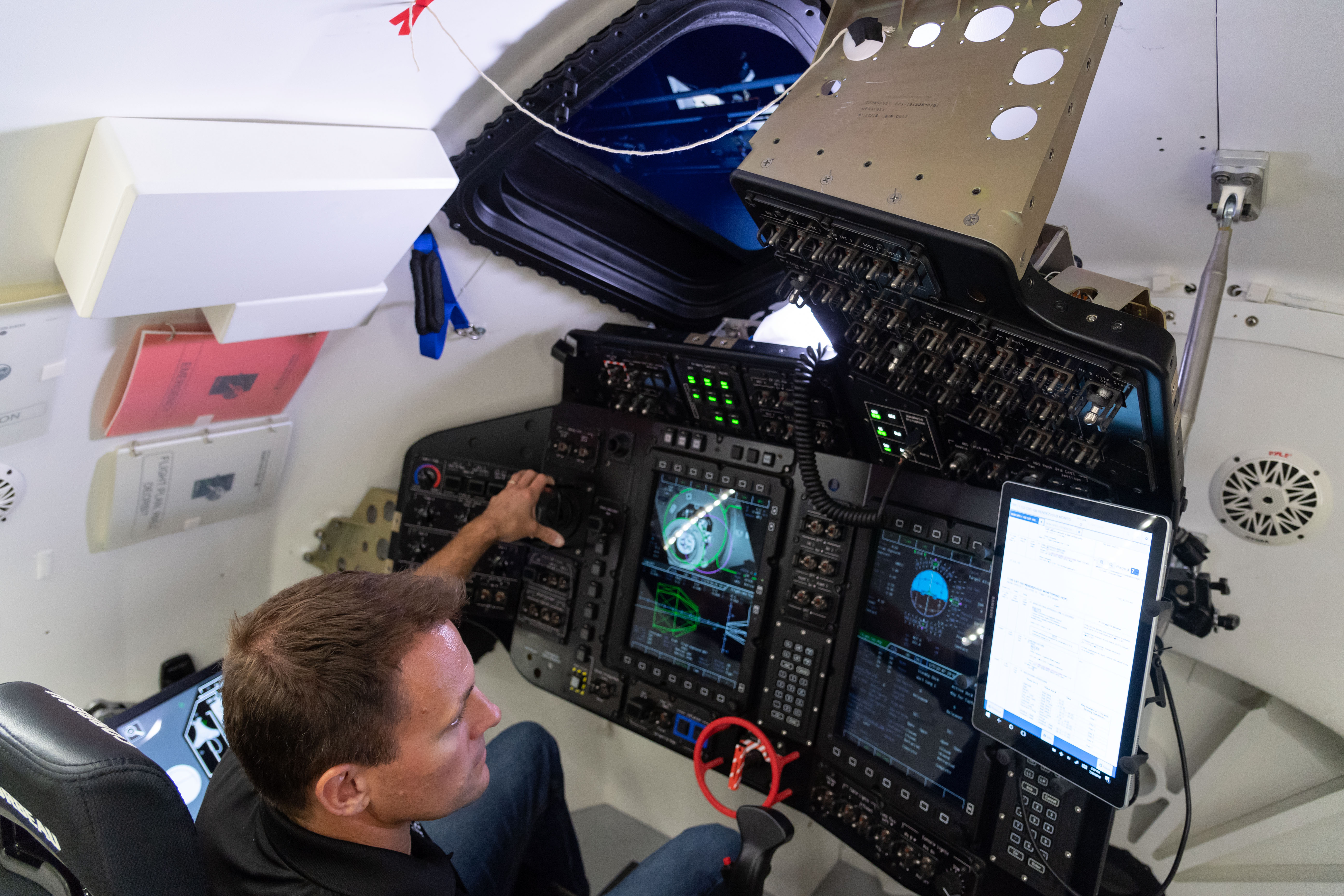
Toggle switches are still there on newer spacecraft, with the addition of large multi-function displays, like on the Boeing Starliner:
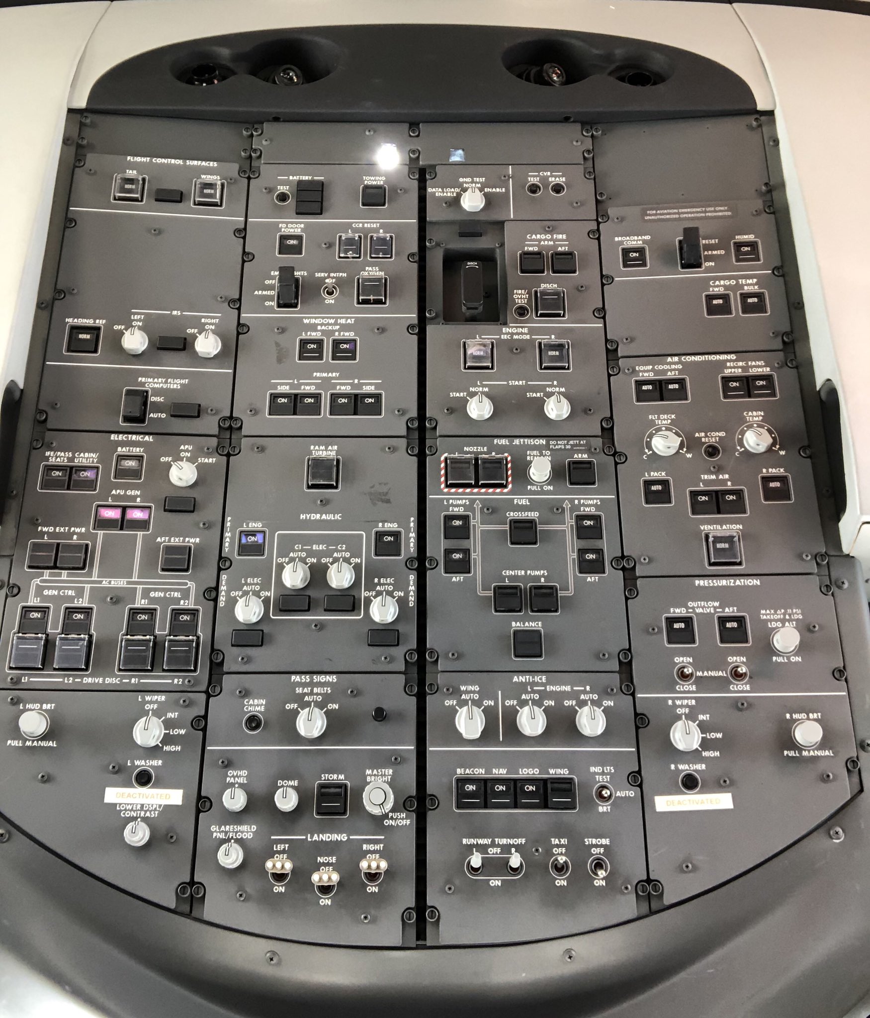
Modern airliner cockpits on the other hand tend to replace most of the toggle switches with things called korry switches, push buttons with two independently illuminated indicators. For example, here’s what the 787 overhead panel looks like:
Also, there are a lot of resources to be found in the broader flight sim community. I took inspiration from two projects in particular:
- The Warthog Project: a DIY A-10C Thunderbolt II ‘Warthog’ Flight Simulator
- https://forum.dcs.world/topic/210303-making-panels-project-log: panels for a F/A-18 Hornet
Design
There are a lot of things you can do in KSP, but for the sake of example, let’s say we choose to go to the Mun (the moon analogue of the kerbolar system). To fly this mission with only the controller, we need at least:
- a joystick to control the attitude of the rocket and spacecraft
- buttons to control the Stability Augmentation System (automatic attitude control)
- buttons to start the next stage of the rocket/spacecraft
- a throttle for powered descent on the mun
- switch to extend/retract the landing legs
- controls for planning orbital maneuvers
- if we want to do it Apollo-style, controls for docking/undocking
Plus there are a lot of other spacecraft systems that you may want to play with: lights, solar panels, radiators, parachutes, action groups etc.
In the end I decided to split inputs into groups and place them onto modules. This way the controller can be extended by replacing/adding new modules. Also, any mistake I made during construction will be limited to one module, so I don’t have to throw everything away on every mistake.
Then I made a sketch to figure out the layout of the modules on the controller:
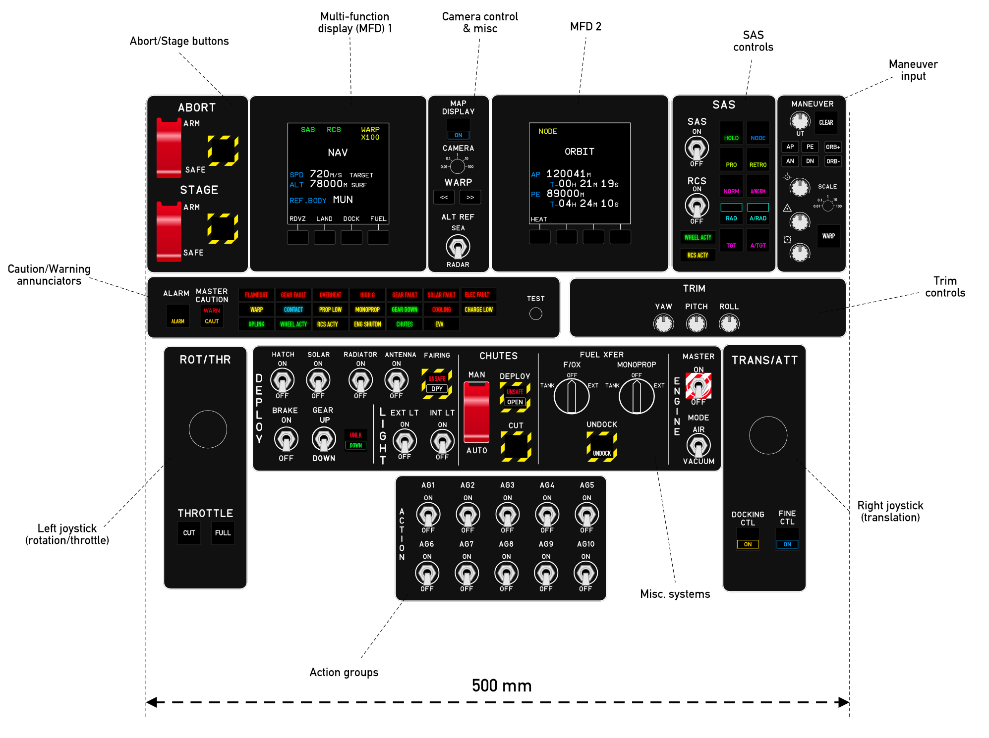 Rough sketch of the modules
For the inputs, I decided to use a mix of toggle switches, rotary switches, illuminated push buttons and custom korry-style buttons (more on that later). In addition, I (optimistically) put two multi-function displays (MFD) in the design to display mission status and the navball, and a panel with caution & warning lights (annunciators). In total the footprint of the controller is about 50 cm wide and 35 cm deep.
Components
Inputs
I bought these:
- Toggle switches. These are the “big” ones, not the “mini” toggle switches. I would have liked something with a paddle design like on the Apollo panels but I couldn’t find anything in the “hobbyist” price range.
- Rotary encoders, for the “MANEUVER” and “TRIM” module
- LED push buttons for the abort & stage buttons
I’ll also need rotary selectors but not sure which ones yet.
Multi-function displays
For now, I bought only one display: a HyperPixel 4.0 Square Non-touch and a Raspberry Pi Zero W to drive it. The display has a resolution of 720×720 pixels (254 PPI), which is nice. The Pi Zero is smaller than the screen so the total footprint is very small.
Joysticks
I bought two industrial joystick switches from amazon (this one, I think). They have only four positions but I chose this instead of analog joysticks because they look more “heavy duty” and they have a nice “clicking” feeling when a contact is made. Not sure how that feels in game though…

Together they have 4 axes, I’m not sure yet of how I will map that to attitude/translation controls. I might end up replacing them with 3-axis analog joysticks (these ones seem to be popular on /r/KerbalControllers).
Construction progress
So far I’ve built a crude frame to hold the modules, and made a prototype module to test the painting and engraving process. I’ve also played around with software & electronics, but I made little progress on that front.
Frame
I needed something rigid to mount the panels on. I could have made the frame entirely out of laser-cut plywood, but I wanted something sturdier, so I looked at aluminium profiles. Most of them are quite big (the smallest standard size I found that was readily available was 15mm) and this reduces the clearance for components behind the panels.
NOTE: real aircraft panels (like the 787 overhead pictured earlier) are mounted with “Dzus fasteners” on special rails. They come up on ebay sometimes.
At some point I stumbled upon eurorack modular synthesizers and thought that they were the perfect format for a desktop controller (Other people have had the same idea). Plus the rails are thin enough so that clearance is not an issue. There are websites that sell eurorack mounting rails for DIY enthusiasts, so I ordered a bunch (specifically, 104 HP low-profile rails, 4 single and 2 doubles), and built a (temporary) frame with the sides made of 5mm laser-cut plywood:
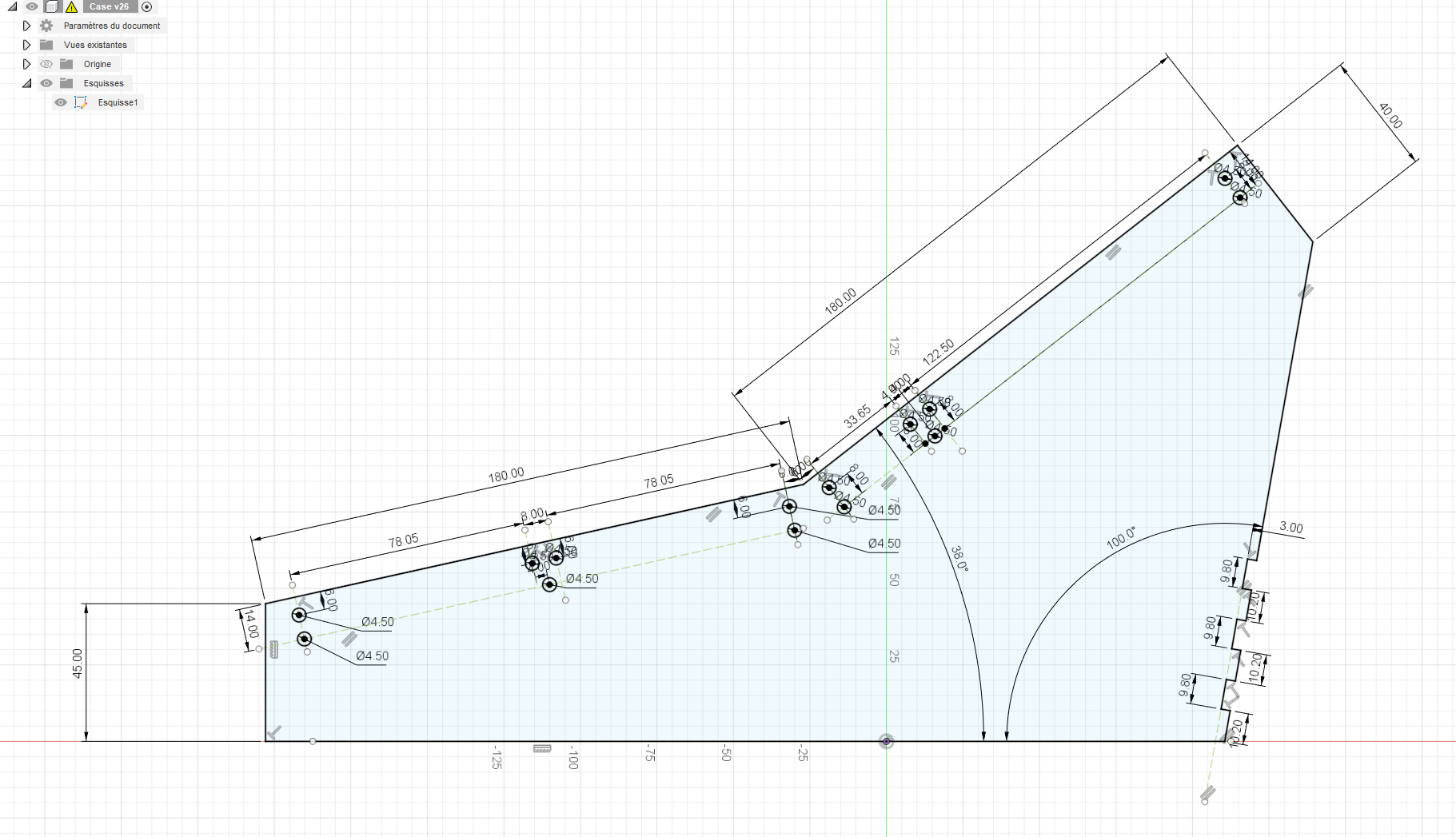
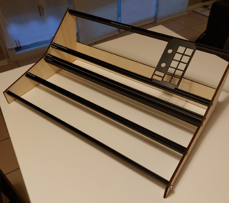
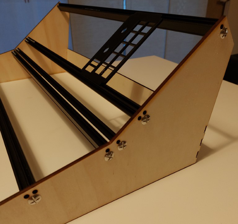
As you can see the whole thing looks very similar to a crude eurorack case. It is approximately 20cm tall, just small enough to not obstruct the view of my monitor. The heights between the rails is, from top to bottom: 3U, 1U, 2U and 2U. I wanted the height of the modules to have standard rack sizes just in case. The design of the frame and the modules went hand-in-hand: I had to modify the design of the modules to accomodate for the heights.
In the end I’m satisfied with the result. The frame feels quite sturdy already and it shouldn’t be a problem to mount reasonably heavy components on it. Still, I’ll probably replace the sides with something more professional-looking in the future.
One thing that I don’t like though is that eurorack module screws are very small (M3) compared to Dzus screws found in aircraft. I suppose that’s a necessary sacrifice for making something small enough to fit on a desk.
Panel prototype
Fabrication
I spent a long time thinking about how to make the module panels and print the labels on them. 3D printing isn’t feasible because of the large size of the panels, so laser-cut plastic sheets seemed to be the best bet.
Unfortunately, at the time, fablabs with equipment to do that kind of work were closed because of COVID. I did a small test with a local business that did laser cutting, and while it wasn’t that expensive it didn’t work out in the end due to the limited choice of material. Eventually fablabs reopened and I went to a local one where you can book access to a laser-cutting machine (a Trotec Speedy 100) by the hour. More on that later.
For the panel material, I chose acrylic sheets (a.k.a plexiglas and a whole lot of other names) as it is cheap and comes in a wide variety of types and colors. I considered three options for the labels:
- engrave text on a black acrylic sheet and fill the grooves with white paint
- cut the panel out of white PMMA, paint it black, and engrave the text on top of the painted panel to reveal the white plastic below
- use two-layer acrylic sheets (e.g. https://www.trotec-materials.com/laser-materials/plastic/trolase.html): same engraving process as above, but no need to paint
I went with option 2, as this gives me more control over the appearance of the panel.
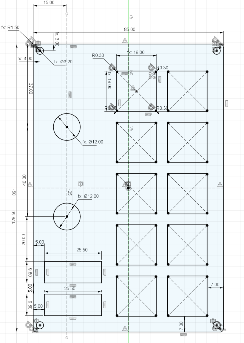
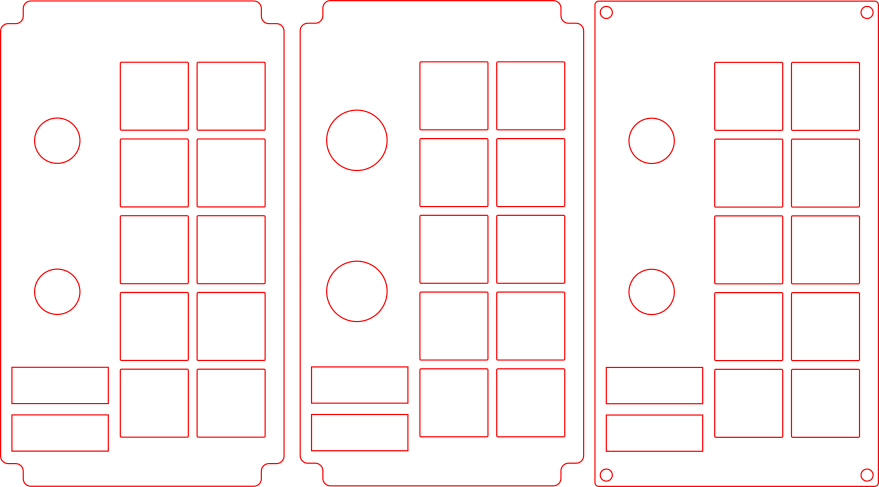
Layout
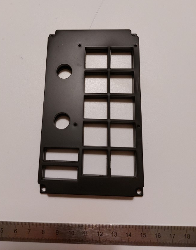
It follows basically the same process as described here. The prototype module panel is made of three layers:
- the bottom layer, on which the toggle switches are mounted
- the middle layer, which hides the mounting nuts of the toggle switches. The holes for the toggle switches are a bit bigger on this layer.
- the top layer, with the engraved text.
RANT: I designed the layers in fusion 360 and that was OK, but the complete workflow is atrocious: I can’t send the fusion 360 sketch directly to the laser cutter, so first I had to export it to DXF, then import it in inkscape to adjust stroke colors and widths. This is because the laser cutter software interface is a virtual printer to which you send vector illustrations with exact stroke color and widths that are recognized as cutting paths or engraving paths depending on the color. I understand that this is done to make it more accessible, but there are a lot of things that can (and did) go wrong:
- fusion 360 messing up paths exported to DXF: some paths became disconnected and I had to fix that up in inkscape
- the laser cutter software silently dropping paths with the wrong color or width
- the drawing not showing up at all on the software because I accidentally added a 0.01 radius gaussian blur on top of my picture in inkscape (wasted an hour at the fablab because of that)
- overlapping duplicated paths: of course the software doesn’t warn you about that. And if you don’t catch it before starting the cutting job, the machine will make two passes, doubling the duration of the job and potentially ruining the whole piece.
NOTE: A few thoughts about the laser-cutting process:
- It’s best to prepare as much things as possible before being in front of the machine, but without access to the laser cutter software to check that the vector paths are recognized, the best you can do is blindly set the colors and widths to the expected values and hope for the best.
- The first time, there will be problems that you find while sitting in front of the machine, so you need to be conservative in your time estimates.
- Ideally the sheets to cut should be perfectly flat. Most of the sheets I had were slightly warped, even those I got from the fablab. This affects the precision of the cut.
- Be prepared to make adjustments on the final piece: for instance, I had to enlarge the middle hole for the mounting nuts because I wrote down the wrong diameter (17mm while should have been at least 18mm).
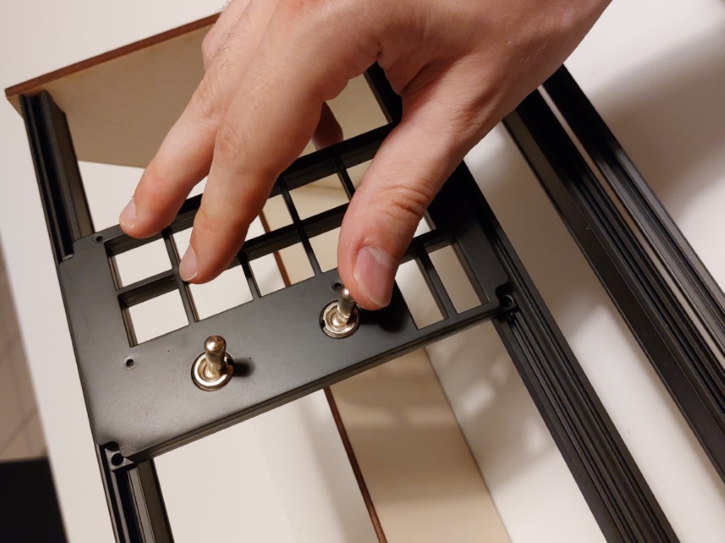
I made each layer out of 3mm thick translucent white acrylic. I went with translucent to allow backlit labels (although it’s not a priority right now). After cutting I painted the top layer black, with a matte black rattle-can spray paint on top of a primer. Here’s the result:
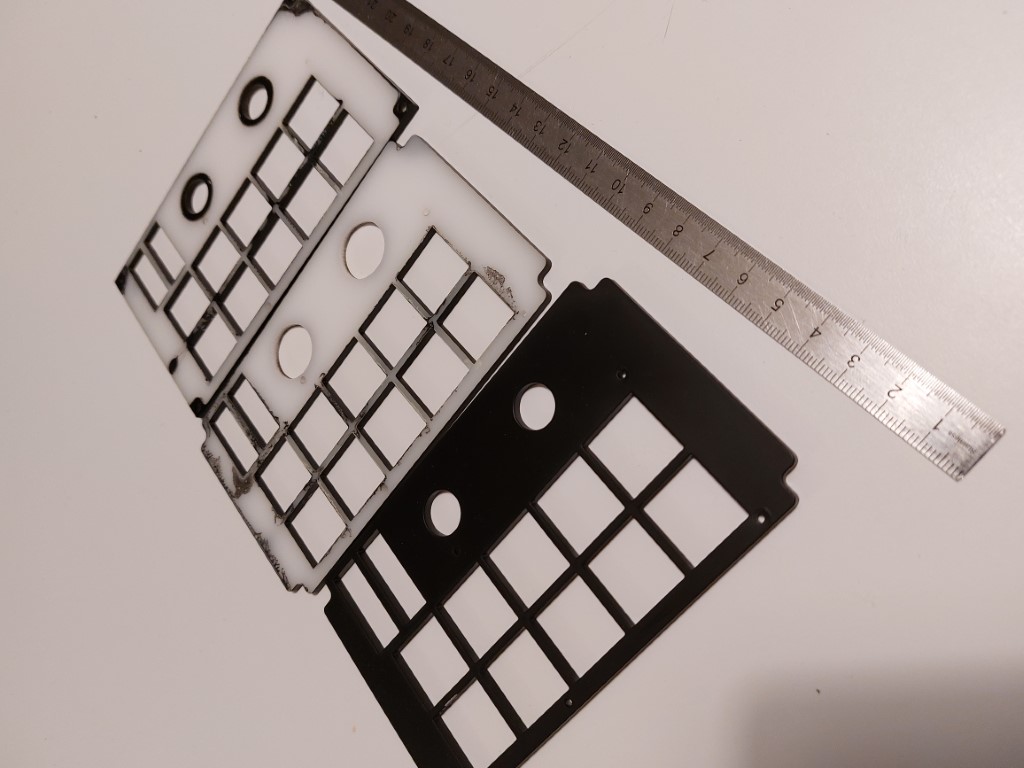
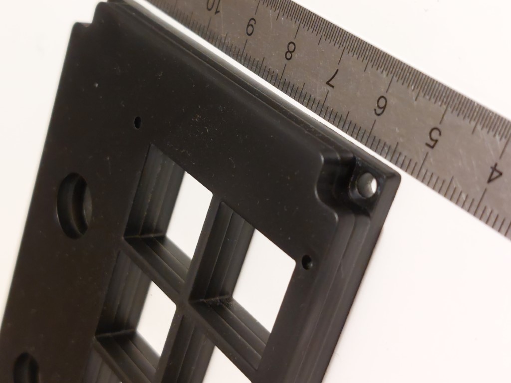
I’m not entirely satisfied with the paint coat: I struggled to make it even and some parts are noticeably glossier than others. Obviously, the next step is to engrave the text… but I haven’t gotten around to it. I have to book another hour at the fablab, and I figured I should wait until I have more stuff to do there to make it worthwhile. Hopefully there will be another post about that soon.
In retrospect, I learnt a lot from such a small part of the project. Having never designed a physical thing from scratch before, I was surprised at the amount of things that can go wrong in the process. It’s quite fun though!
Korry buttons
For some reason I think that korry switches look cool, so I wanted some in my controller. Unfortunately, real korry switches, being certified flight hardware, are hopelessly expensive (around $100 per switch) and usually out of reach for hobbyists. Sometimes surplus switches show up on ebay, but you don’t really get a choice of labels. There exists professional-looking reproductions of korrys for flight simulators that are more affordable, but they are still expensive if you need more than a couple. Fortunately, DIY cockpit builders have devised ways to build convincing replicas 1, so I followed a similar approach.
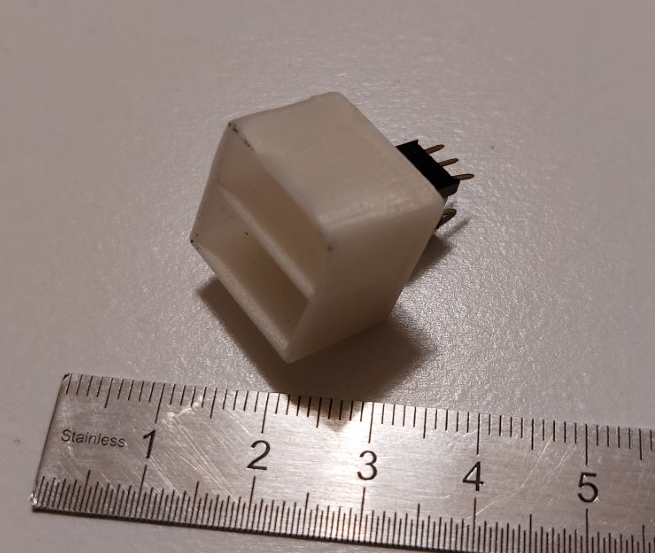
First, I asked a friend to 3D-print a bunch of LED boxes (thanks!). I used this design by edouardallez on thingiverse.
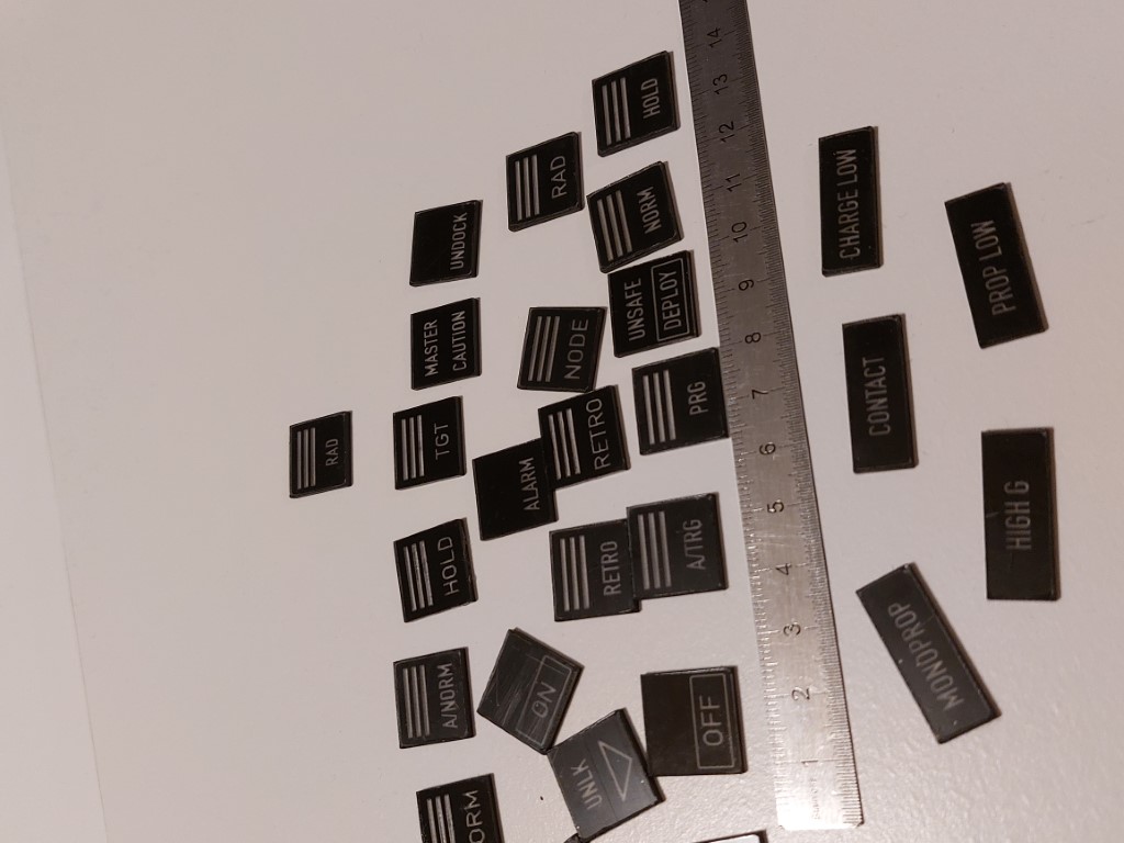
I made the button faces out of 1.5mm reverse-laserable black/transparent PMMA laminate: basically, it’s a clear plexiglas sheet coated with an opaque layer that you can remove with a laser engraver or a CNC router (as I understand, it’s mostly used for signage).
Then I glued “diffusers” behind each button face: these are necessary to diffuse the light of the LED evenly across the label. They are 6mm thick and made out of translucent white acrylic (same as the panel).
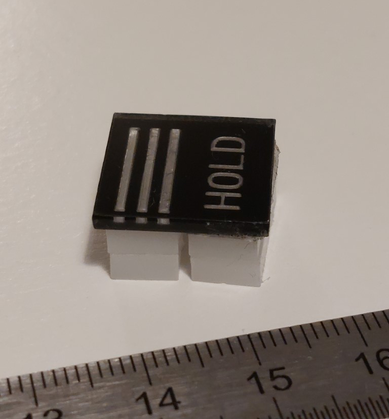
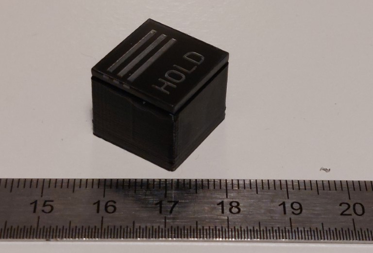
Here’s the assembled button with the LED box painted black and the face:
… and with LEDs:
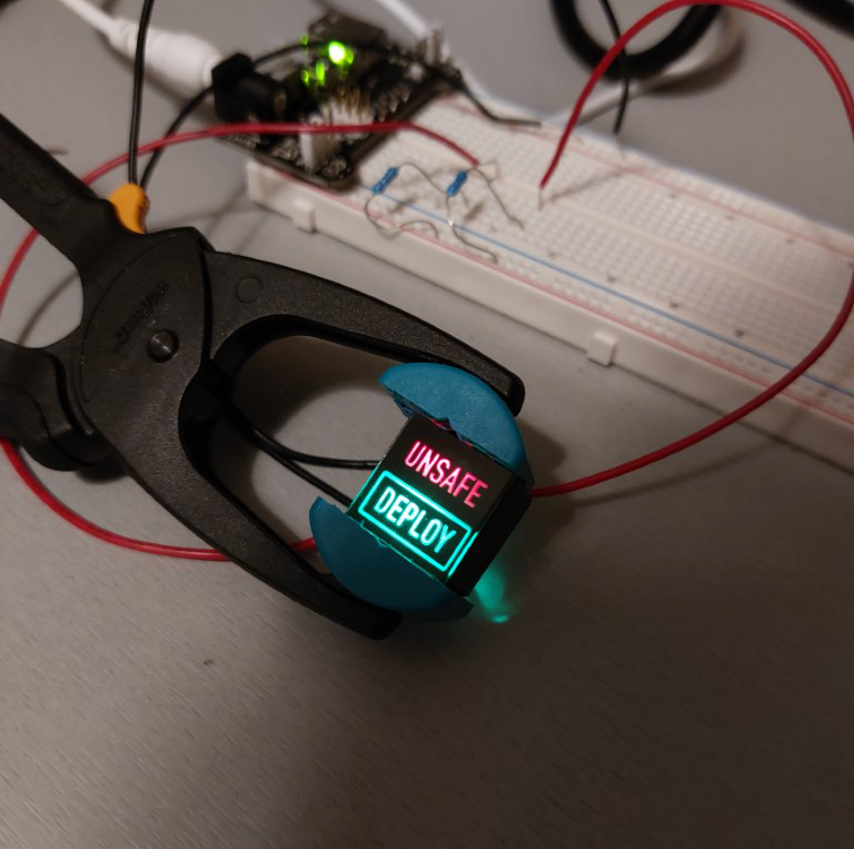
My main worry was light bleeding between the top & bottom parts, but fortunately that wasn’t the case with multiple coats of black paint. The picture above was actually taken with 3mm diffusers instead of 6mm and you can see that the illumination is uneven (you can somewhat make out the position of the LEDs behind). So 6mm thick diffusers are definitely needed.
There are a few things to improve with the current design. First, the LED boxes are too small: with the 6mm diffusers the LEDs barely fit inside and the LED pins are bent uncomfortably. I’m not entirely satified about the labels either: compared to real korrys, you can clearly make out the label when it’s not illuminated. I think this is due to light backscattering on the engraved portions of labels. I’m not sure yet how to fix this.
Another issue is the mounting of the buttons on the panels: initially, my plan was to glue switches behind the buttons, solder the resulting assemblies onto a circuit board, and stick that behind the panels. But the more I think about this the more I’m worried that the buttons might “wobble” when pressed since there’s no rail or shaft to keep them straight during travel, unlike real korrys. I might need to rethink the design entirely if that proves to be a problem.
Electronics & software
I didn’t do much on the electronics & software front. I did some tests with an Arduino Mega 2560, but the I/O on that board probably won’t be enough. I have some proof of concept arduino code and a mod for communication with the game via a serial-over-USB connection, but that’s about it. To be honest, I find the “physical” part of the build much more interesting.
Multi-function display
I spent a few week-ends tinkering with the Raspberry Pi and the HyperPixel 4 and managed to draw text & vector graphics controlled remotely via an USB connection:
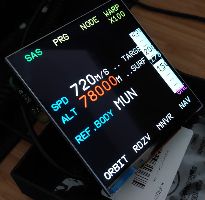
This was much more troublesome than I expected, mostly because of software issues (the hardware is fine) and the poor state of cross-platform development in general. The story is too long and tedious to fit in this post, so it will have to wait for a future post/rant.
Conclusion
That’s all for this time. It took longer than expected to write down all this stuff, and some of it might become obsolete as the design evolves, but it’s useful to be able to look back on early designs, if only to avoid making the same mistakes.
The next post will probably be about engraving the labels on the panels. See you then!